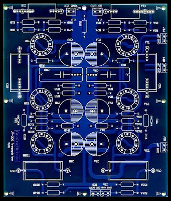
FEATURE 特徴
1. 1。 Circuit design is with reference to the classical Jadis JP-200. 回路設計の古典的なJadis金鍾泌自民連総裁参照されて200。
2. 12AX7 x 6 pcs for amplfication. 2。amplficationの12AX7 × 6個。
3. 3。 Independent power supplies for tube power and tube filaments. 管電力管フィラメントの独立した電源を供給します。
3. 3。 Independent power supplies for tube power and tube filaments. 管電力管フィラメントの独立した電源を供給します。
4. 4。 Double blue layer PCB, dimension of 210mmx180mm, 2.5mm thickness and 2oz copper. ダブル青層PCB、210mmx180mm、2.5mmの厚さと2オンス銅のディメンションです。


Optional: オプション:
1. 1。 Adjustable Tube Power Supply 250V-400V 12.6V(1.5A)x2 / 6.3V(1.5A)x2 for Tube Preamplifier 調整可能なチューブ電源250V - 400V〜12.6Vの(1.5aを)× 2 / 6.3V(1.5aを)× 2チューブプリアンプ用
2. 2。 Power Transformer T120 電力用変圧器T120

1. 1。 Adjustable Tube Power Supply 250V-400V 12.6V(1.5A)x2 / 6.3V(1.5A)x2 for Tube Preamplifier 調整可能なチューブ電源250V - 400V〜12.6Vの(1.5aを)× 2 / 6.3V(1.5aを)× 2チューブプリアンプ用
2. 2。 Power Transformer T120 電力用変圧器T120

Critial Note in Assembly: 国会でCritial注:
1. 1。 Connecter J3B is B+ (400 VDC) - you could slightly change it to boost the sound performance. The marking is incorrect. コネクターJ3BはB +(400 VDC)を-に少しだけのサウンドパフォーマンスを高めるに変更することができます。 マーキングが間違っています。 The marking "AC" should be connected to "GND", whereas "GND" should be connected to "B+". "交流の"GND""にの"GND"の"B +"に接続する必要が一方に接続する必要がありますマーキング。
2. 2。 Connecter 12.6V J4A and J4B is filament voltage for tubes . (The marking should be "DC" instead of "AC") コネクター12.6VのJ4AとJ4B管用フィラメント電圧です (マーキング、"直流"ではなく"交流")する必要があります 
SIMULATION RESULTS シミュレーション結果
DC Analysis: 直流解析:

FILES DOWNLOAD ファイルのダウンロード
JP200 preamplifier schematic JP200プリアンプ回路図
JP200 preamplifier BOM JP200プリアンプのBOM
No comments:
Post a Comment