Wednesday, October 28, 2009

PCM58/PCM1702/PCM1704 & CS8414 DAC DIY Kit PCM58/PCM1702/PCM1704&CS8414 DACのDIYのキット


OVERVIEW 一般情報
This DIY kit uses DAC IC pcm58p/pcm 1702/pcm1704 (with adaptor PCB).これはDIYのキットのアダプタ基板()DACをIcをpcm58p/pcm 1702/pcm1704を使用します。 CD digital receiver IC CS8412/CS8414 and digital filter DF1700/SM5813. CDはデジタルレシーバIC CS8412/CS8414およびディジタルフィルタのDF1700/SM5813。 It requires main power supply 12VACX4, 18VACX2 and 20VACX4.これは主電源12VACX4、18VACX2と20VACX4必要があります。 The PCB thickness is 2mm and copper 2oz.基板さ2mm、 銅2オンスです

Each AC supply is regulated to provide 5V, -12V and +/-18V with VR tunning to supply power to the ICs. 各AC電源、5Vを提供するために規制されて- 12Vと+ / - 18VのVRで抵抗器に電力を供給するtunning。 The regulator used is LM1086 providing 1.5A low dropout regulation. レギュレータLM1086 1.5aを低ドロップアウトの調節を提供して使用されます。

This kit also includes a relay protection and NPN switch shutdown as a startup circuit and protection circuit このキットはまたスタートアップ回路と保護回路としてリレーの保護とNPNスイッチのシャットダウンが含まれて

The analog output from PCM58 is buffered by NE5532 low noise amplifer and ac-coupled by 10UF Cap. PCM58からのアナログ出力NE5532、低ノイズアンプとACによってバッファに格納されて.47キャップによって結合。 For low distortion, good matching and low noise performance, RFIA 10UF cap is also provided as Deluxe version. 低歪みについては、良い一致すると低ノイズ性能、RFIA .47キャップもデラックス版として提供されます

The DIY Kit: DIYのキット:


The IC package: ICパッケージ:


PCM1702/PCM1704 adaptor module: PCM1702/PCM1704アダプタモジュール:


Parallel 4 PCM58/PCM1702/PCM1704 DAC:並列4 PCM58/PCM1702/PCM1704 DACの:


FILES DOWNLOAD ファイルのダウンロード
PCM58/PCM1702/PCM1704 DAC schematic PCM58/PCM1702/PCM1704 DACの回路図
PCM58/PCM702/PCM1704 BOM PCM58/PCM702/PCM1704のBOM
PCM58P datasheet PCM58Pデータシート
NE5534 datasheet NE5534データシート
TORX176 datasheet TORX176データシート
LM1086 LM1086

Dale VISHAY Resistor 23 Steps Ladder Type Attenuator for Volume Control デールビシェイ抵抗23ボリュームコントロールラダー型アッテネータのステップ


OVERVIEW 一般情報
1. Dale resistors , 23 step attenuator and knob . 1。 デールの抵抗 、23のステップアッテネータノブ
2. 2。 Ladder type structure, 23 sections. はしご型の構造、23のセクション。
3. 3。 Log scale attenuation. ログスケールの減衰。
4. 4。 Rotary are Made-before-break ロータリーの前に改製されます

The DIY Kit come with a resistor pack, 23 step rotary, and aluminum knob. DIYのキットには抵抗パック、23ステップのロータリー、アルミニウム製のノブを使って来る。 The available values are 10k, 50k, 100k, and 250k ohm. 使用可能な値10kと5万、10万と25万オームです。


ASSEMBLY GUIDE 組み立てガイド
The circuit diagram displays the configuration of the serial resistor network (ladder type) which consists of Rin and Rg.回路図では、シリアル抵抗ネットワークは、りんとRgの構成(はしご型)の設定が表示されます。 For one channel, there are 23 pair of Rin and Rg. 1つのチャネルについては、りんとRgの23のペアです。 The total equivalent resistance R=Rin + Rg, this value are fixed, so that the input resistance is more or less the same (ideally we want it to be constant)総等価抵抗R =凛+ 0805は、この値なので、固定されては、入力抵抗は、多かれ少なかれ同じです(理想的にそれを定数とすること)する


Procedures to assembly:アセンブリへの手続き:
1. 1。 Identify the resistor values (Rin and Rg) for two channels according to the following resistor list (10k, 50k, 100k and 250k). 2つのチャネルは以下の抵抗器のリストによると(りんとRG)は抵抗値の識別(1万、5万、10万と25万)。 You could paste the resistors by plastic tapes on a paper one by one, where the number of 1 to 23 are marked. またプラスチックテープで紙1上の1つ、ここで23から1の数がマークされて抵抗を貼り付けることができます。
2. 2。 Locate the postion 1, 2, 3, ..., 23 position of channel 1 and channel 2. 位置は1、2、3、見つけて...、チャネル1の23の位置と、2チャネル。
3. 3。 Solder the resistors Rin and then Rg. はんだ付け抵抗りんとして0805。
4. 4。 Connect the GND, signal in, and signal out. は、GNDに信号とを信号に接続します。
5. 5。 Finally, test it and good luck. 最後に、それは幸運をテストします。


The complete one should look like (but the wire colors maybe different in different cases):完全な1つのようになります(ただし、線の色かもしれない別のケースで異なる):


The resistor list for 10k (the resistor values started by position 1 and till to position 23): 10kの抵抗器リスト(抵抗器の位置1と位置を23日まで)の開始値:

The resistor list for 50k (the resistor values started by position 1 and till to position 23): 5万の抵抗一覧(抵抗器の位置1と位置を23日まで)の開始値:


The resistor list for 100k (the resistor values started by position 1 and till to position 23): 100,000の抵抗一覧(抵抗器の位置1と位置を23日まで)の開始値:


The resistor list for 250k (the resistor values started by position 1 and till to position 23): 25万の抵抗一覧(抵抗器の位置1と位置を23日まで)の開始値:

ALPS Potentiometer (Attenuator) for Volume Control (2 Channels) アルプス電気ポテンショメータ(アッテネータ)ボリュームコントロール(2チャンネル)


OVERVIEW 一般情報

The most important feature of a dual audio-taper attenuator (which I'll just call a potentiometer from here on) is how well it tracks: that is, how closely matched the two channels are to each other.デュアルオーディオの最も重要な機能(私はここから)ポテンショメータと呼びますアッテネータテーパどのようにうまくトラック:つまり、どのように密接に2つのチャネルマッチングお互いにされています。 No volume control has perfect tracking: one channel will always have a little different from the other.いいえボリュームコントロールを追跡完璧があります:1つのチャネルは、常に少し他とは異なる必要があります。 Even well-trained ears are only sensitive enough to notice a difference of about 1dB, though, and for the average person the minimum noticeable difference is more like 3dB.も、よく訓練された耳には十分な約1dBの違いに気付くことにも敏感で、最低限の顕著な違いは3デシベル以上のようにされている平均的な人です。

ALPS 27mm Size Metal Shaft Potentiometer RK27 Series offers comfortable operation and possess high, precise features, ideal for audio applications.アルプス電気27mmのサイズ金属シャフトポテンショメータRK27シリーズと、正確な機能は、オーディオアプリケーションに最適な高性能を持つ快適な操作性を提供します。

The following shows a typical ALPS RK27 dual channels potentiometer.次の典型のALPS RK27デュアルチャネルポテンショメータを示しています。 As we can see, there are 2 rows of pins and each row is for one channel.我々を参照できますが、ピンの2行と行ごとに1つのチャンネルです。 Each row having 3 pins, which are INPUT, OUTPUT and GND.それぞれの行は入力、出力とGNDが3ピンを持つ。 There is one control bar, andy by rotation the bar, the two channels volume can be synchronizly adjusted.ある1つのコントロールバー、回転アンディバーは、2つのチャネルのボリュームsynchronizlyを調整することができます。 Notice that each potentiometer is independent of each other having individual input, output and gnd.通知は、各ポテンショメータは、個々の入力、出力とGNDを持つ他の独立しています。


There are different resistance could be chosen for RK27 series (10K, 100K and 250K). (の10KがRK27シリーズに選ばれる可能性が別の抵抗が10万と25万)。 We should identify the resistance and the footprint before using the product.私たちは、フットプリントの製品を使用する前の抵抗値を識別する必要があります。

Take a 10K attenuator as an example.例として10Kアッテネータください。 Rotate the shaft anticlockwise until the shaft cannot be rotated.までの軸が回転することはできません軸反時計回りに回転させます。 Then use a multimeter to measure any two pins within one row until a pair of pins is measured to be 10K Ohm.その後、1行の中の任意の2つの端子を測定するためのピンのペアまで、マルチメータを使用する10Kするオームの測定されます。 Then rotat the shaft in reverse direction until the shaft cannot be rotated.までの軸が回転することはできませんし、逆の方向に軸rotat。 The two pins measured should also be 10K Ohm. 2つの端子がありますまた、10Kがオームを測定した。 This can identify the pair of pins is IN and GND and the one left is OUT.このINとGNDの1つの左に切れていますピンのペアを識別することができます。 If the pairs of pins measured is 0Ohm, then choose other pins within the row to measure again until 10K Ohm could be mesaured no matter rotate the shaft anticlockwise or clockwise at maximum condition.もしピンの測定のペア0Ohm、その行以内に再度10kΩのまでを測定するために関係なく、最高の状態で軸反時計回りまたは右回りに回転mesauredことができる他のピンを選択しています。


FILES DOWNLOAD ファイルのダウンロード
ALPS RK271 potentiometer datasheet アルプス電気RK271ポテンショメータデータシート

IR Remote Control VR with Motor (6 Channels) IRリモートコントロールVRの汽車と(6チャンネル)


FEATURES 特徴
1. 1。 IR remote control (Supports RC-5 IR protocol and most remote control) IRリモートコントロール(サポートのRC - 5赤外線プロトコルほとんどの制御リモート)
2. 2。 Audio volume control supports up to 6 single-end signals or 3 balanced signals . オーディオボリュームコントロールをサポートする6のシングルエンド信号または3の平衡信号
3. 3。 Functions with mute and power on/off . と機能をミュート電源オン/オフ
4. This kit uses ALPS 6 channe l motor VR , Nichicon and WIMA capacitors, Dale resistors. 4。 このキットにはアルプス電気6 channe リットル モーターVRはメーカーWIMAコンデンサ、 デールの抵抗を使用します
5. 5。 Power supply requires 9-15V DC 電源 :DC 9 - 15Vを必要と
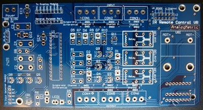
6. 6。 PCB dimension: 150mm x 78mm, thickness 2.5mm, with 2oz copper . 基板寸法:150ミリメートルXの78ミリメートル、2オンス銅の厚さ2.5ミリメートル。

Extensions: this kit can be used with input/channel selector DIY kit and LCD module DIY kit. 拡張子:このキットの入力と一緒に使用することができます/チャネルセレクタのDIYキットとLCDモジュールのDIYキットです。

This kit can use with any other remote control as long as it can support RC-5 IR protocol which are made by Philips. このキットにはレッドカードをサポートすることができますがPhilips社により作られています5赤外線プロトコル限り他のリモートコントロールで使用することができます。

The RC-5 code from Philips is possibly the most used protocol by hobbyists, probably because of the wide availability of cheap remote controls.は、RC - Philipsから5のコードの可能性がある格安のリモートコントロールの広い空のせいか、愛好家では、最も使用されるプロトコルです。 The protocol is well defined for different device types ensuring compatibility with your whole entertainment system.プロトコルだけでなく、別のデバイスタイプのあなたの全体のエンターテイメントシステムとの互換性を確保するために定義されます。 Lately Philips started using a new protocol called RC-6 which has more features...最近ではフィリップスの新しいプロトコルをレッドカードと呼ば- 6は、より多くの機能が使用して起動... For more detail, please refer the following link:詳細については、次のリンクを参照してください:

http://www.sbprojects.com/knowledge/ir/rc5.htm http://www.sbprojects.com/knowledge/ir/rc5.htm

ASSEMBLY GUIDE 組み立てガイド
1. 1。 Measure the output voltage of the regulator LM7805 (PIN #3) to be +5V. 測定はレギュレータLM7805の出力電圧を#3()PINを+5 Vにする
2. 2。 Check the IR Reciever by pressing the Power bottom of IR Remote controller. IRリモートコントローラの電源の下を押すと、IR受信を確認します。 If work,the LED (Power indicator) will grow up (Power on). 作業しなければ、LED(電源インジケータ)を開く(パワー)を成長されます。
3. 3。 Press Vol+,Vol-, #1,#2,#3,#4 and mute button and see the responses of the IR board. プレス集+巻、#1、#2、#3、#4、ミュートボタンを参照してくださいIR情報委員会の反応。
4. 4。 If the display module is used, please use jumpers to short the sensing selection pins on the right corner of the board. 場合はディスプレイモジュールを使用する場合、ボードの右上隅にはセンサの選択ピンを短くするために使用ジャンパしてください。 Then 5 single-end signals or 2 differential signals can be used 次に、5のシングルエンド信号または2の差動信号を使用することができます
5. 5。 If the display module is not used, please use jumpers to short the 6th channel selection pins on the right corner of the board.Therefore, 6 single-end signals or 3 differential signals can be used. 場合はディスプレイモジュールを使用していない場合は、board.Therefore、6のシングルエンド信号または3の差動信号を使用することができるの右上隅には6チャネルの選択ピンを短くするために使用ジャンパしてください。
6. 6。 IR receiver should be soldered in upward direction and be faced in opposite to the board, so as to increase the sensitivity of receiving (sensing Area) from remote control. IRレシーバ上向き方向に半田付けする必要があるボードの向かいに直面しているので、として受信感度を上げる()をリモコンからエリアを感知。


FILES DOWNLOADファイルのダウンロード

IR Remote Control VR Schematic IRリモートコントロールVRの回路図
IR Remote Control VR BOM IRリモートコントロールVRのBOMを

REFERENCES 関連情報

http://www.sbprojects.com/knowledge/ir/rc5.htm http://www.sbprojects.com/knowledge/ir/rc5.htm

Infra-red remtoe control transmitter RC-5 SAA3010 赤外線remtoeコントロールトランスミッタレッドカード- 5 SAA3010

Applicaces Remote Control Project by Rucha R. Lakhe, et.al. ApplicacesリモートコントロールプロジェクトRucha R. Lakhe、et.al.による

Variable DC Power Regulator 0-24V (5A) 可変DC電源レギュレータ0 - 24V(5A以上)


FEATURES 特徴
1. 1。 Delivery current up to 5A for each channel, variable output voltage from 0-24VDC depending of the power transformers. 配信を現在の最大 5Aの0から各チャンネルに、可変出力電圧のため0603の電源変圧器によって異なります。
2. 2。 Connect modules in series or parallel to provide either higher output voltage range or higher output current. シリーズのモジュールまたはパラレル接続のいずれかより高い出力電圧範囲以上の出力電流を提供します。
3. 3。 Use of low dropout regulator LM1084 with line regulation of 0.015% typica, load regulation of 0.1% typical. 0.015%typica、0.1%、典型的な負荷レギュレーションのラインレギュレーションは低ドロップアウトレギュレータLM1084の使用。
4. 4。 Ripple rejection of 75dB and RMS output noise 0.003%. 75デシベルとのリップル除去率RMS出力ノイズ:0.003%。
5. 5。 Use of Nichicon capacitor and Da le resistors. を使用するメーカーのコンデンサとル抵抗。
6. 2.4mm PCB and 2oz copper and dimension: 99.5mm x 43mm. 6。2.4ミリメートル 、PCBと2オンス 寸法:99.5ミリメートルXの43ミリメートル。


ASSEMBLY GUIDE組み立てガイド

1. 1。 Solder all the components according to the schematic and the BOM.とは、BOMの回路図によると、はんだのすべてのコンポーネント。
2. 2。 Connect 12V AC of secondary coil of the transformer for 9V DC or 18V AC for 12V DC. 12Vの直流用12VのAC 9V DCまたは18Vの交流のためのトランスの二次コイルを接続します。 The input to output voltage drop is about 1V.出力電圧が低下し、入力1Vの情報です。 That is for high output voltage, apply 1V higher voltage for input.は、高出力電圧は、入力に1Vの高電圧を印加している。
3. 3。 Without connecting any loading (open output), use a voltmeter to measure the output voltage.任意の読み込み(オープン出力)、出力電圧を測定する電圧計を使用する接続がない。 The output voltage can be adjusted by the resistor trimmer.出力電圧は、抵抗トリマで調整することができます。
4. 4。 Good luck.頑張って。

FILES DOWNLOADファイルのダウンロード

Variable DC Power Regulator Schematic 可変DC電源レギュレータ回路図

Variable DC Power Regulator BOM 可変DC電源レギュレータのBOM


TEST RESULTS テスト結果

Output ripply voltage at 9V DC output is shown in the following figure. 9V DC出力時の出力さざ波の電圧は、次の図に示されています。
The ripple voltage Vpp = 2.56mVリップル電圧Vppの= 2.56mV
Line Regulation = (2.56mV / 9V) * 100% =0.0284%ラインレギュレーション=(2.56mV / 9V)の* 100%= 0.0284パーセント

Variable Tube Power Regulator 190V-450V (100mA) & 0-15V (1.5A) x2 変数のチューブパワーレギュレータ190V - 450V(100mA)を&0 - 15Vを(1.5aを)× 2


FEATURE 特徴

190-380V or 250-450V DC (100mA) for tube preamplifier 190 - 380Vまたは 250 - 450V 直流(100mA)の 管プリアンプ用
0-15V DC (1.5A) x2 for tube filaments / other applications 0 - 15Vの直流(1.5aを)× 2 管フィラメント用/他のアプリケーション
1. 1。 Adjustable tube power supply by resistor trimmer for tube preamplifier, for examples, Jadis JP-200, Cary AE-ONE, Marantz 7, etc. 抵抗管プリアンプのトリマで調整可能なチューブ、電源、例については、Jadis JP - 200、ケアリーのAE -ワン、マランツ7、等
2. 2。 Incorporating flexible design: Use 5Z2/5Z3/5U4/6X4/Two diodes as rectifer, EL84/6P14 as voltage regulating tube and EF86/6J8 as buffer tube 柔軟な設計:rectiferとして使用 5Z2/5Z3/5U4/6X4/Twoダイオード 、電圧バッファ管として管 EF86/6J8 規制として EL84/6P14を組み込む
3. 3。 Additional power supply for filament: adjust to 6.3V / 12.6V (1.5A) x2 フィラメントのための追加電源:6.3V / 12.6Vの(1.5Aまで)× 2 を調整する
4. 4。 Double blue layer PCB, 250mmx120mm, PCB thickness of 2.5mm, 2 oz copper metal , come with schematic. ダブル青層PCB、250mmx120mm、2.5mm の2の基板厚オンス銅金属 、回路図が付属。
5. 5。 Socket provided for filtering choke 10H 150mA connection or manually short. ソケット10Hを150mAの接続または手動で短いチョークフィルタリングを提供する。

Optional: Power transformer T120 オプション:電源トランスT120
Optional: Inductor 10H 150mA オプション:インダクタ10Hを150mAの
http://store.analogmetric.com/goods.php?id=69 http://store.analogmetric.com/goods.php?id=69


ASSEMBLY GUIDE 組み立てガイド
1. 1。 Soldering the components according to the schematic and part list which can be downloaded from here. によるとはんだ付けのコンポーネントはここからダウンロードすることができますパーツリストの回路図。
2. 2。 For 190-380V DC output, D1 uses 1N5378B 190 - 380V DC出力d1を 1N5378B を使用して
For 250-450V DC output, D1 uses 1N5383B 250- 450V DC出力d1を 1N5383B を使用して
3. 3。 Connect the power transformer according to the schematic and switch on the power supply (turn it off if found any smokes from transformer or the tubes does not light up properly). もしあればトランスからまたは管を正常に点灯しない場合は喫煙が見つかりましたスケマティックによると電源スイッチは電源トランスの接続()はオフにします。
4. 4。 Measure the voltage across the J4 (Dangerous! Be care of high voltage!) , J6 and J7. を測定するJ4の両端の電圧 (危険!高電圧の世話をしよう !)J6およびJ7。 The voltage of J4 will be gradually increase until reach preset voltage. J4の電圧までのプリセット電圧に達するまで徐々に増加されます。
5. 5。 Output voltage can be adjusted by VR1. 出力電圧VR1を調整することができます。

Ensure all high voltage capacitors are fully discharged after switched off the power supply! 後に電源をオフに切り替えすべての高電圧のコンデンサが完全に排出されていることを確認! (it normally takes few minutes) (正常)は数分かかります


FILES DOWNLOAD ファイルのダウンロード
Variable tube power regulator schematic 変数管電源レギュレータ回路図
Variable tube power regulator BOM 変数のチューブパワーレギュレータのBOM

6N3 (5670) Tube Buffer DIY Kit (2 Channels) 6N3(5670)チューブのバッファのDIYキット(2チャンネル)


FEATURE 特徴
1. 5670/2C51/6N3 tubes are used for two channels buffers with cathode follower configuration . 1。5670/2C51/6N3管 カソードフォロワの構成で2つのチャネルバッファのために使用されます。
2. Provide unity gain and double output power . 2。 ユニティゲインをダブル出力パワーを提供します The tube preamp come with low output resistance and provide high driving capability. チューブプリアンプ低出力抵抗が付属して高い駆動能力を提供します。
3. 3。 For the DVD/HDCD/CD analog output , it produces sweet and deep audio sound after go through the 5670 /6N3 or equivalent tube buffer preamps. DVDの場合/ HDCD / CDのアナログ出力は、5670 / 6N3または同等の管バッファのマイクプリアンプを通過後に甘いと深いオーディオサウンドを生成します。
4. 4。 Simple design, high linearity, low distortion. シンプルなデザイン、高リニアリティ、低歪み。
5. Dale resistor, WIMA and Muse capacitor, and Vishay 1N5062 diode 5。 デール抵抗、WIMAとミューズコンデンサ、およびメーカー1N5062ダイオード
6. 6。 Independently supplies for heater filament to reduce noise coupling. ヒーターフィラメント用の個別電源のノイズカップリングを低減します。
7. 7。 Built-in voltage regulating circuitry 内蔵電圧回路を規制する
8. 8。 Small dimension: 160mmx90mm, 2.5mm thickness and 2oz copper 小寸法:160mmx90mm、2.5mmの厚さと2オンス銅


Optional: Toroid Transformer T20 50W オプション:トロイダルトランスT20 50W
Output Power: 50W 出力電力:50W
Insulating strength: 10Mohm, AC2000V/1min 強度絶縁:10Mohm、AC2000V/1min
Input Voltage (AC): 110-115V /220-230V 入力電圧(AC):110 - 115V / 220 - 230V
Output Voltage (AC): 9-0-9V/1A 出力電圧(AC):9-0-9V/1A
15-0-15V/1A 15-0-15V/1A

ASSEMBLY GUIDE 組み立てガイド
1. 1。 Solder all the components according to the schematic and part list. によるとはんだのすべてのコンポーネントとパーツリストの回路図。 To obtain a unity gain, use R2= 1Kohm and R5=1Kohm instead of short; the short of R2 and R5 is for -6dB attenuation (half voltage gain). ユニティゲインで使用するR2は= 1KohmとR5 = 1Kohm代わりに短いのを入手するには、R2の短いとR5のは- 6dBの減衰量(半分の電圧利得)。
2. 2。 Connect the power transformer 15V-0-15V and 9V-0-9V and ensure the connections are correct. 電源トランス15Vの- 0 - 15Vのおよび9V - 0最低- 9Vを接続し接続が正しいことを確認されます。
3. 3。 Turn on the power supply without put in the tube. チューブに入れることなく電源をオンにします。 Shut down the power supply if the transformer becomes very hot or come out some strange sound; check again the connection of the transformer. 場合は変圧器が非常に熱くなったりいくつかの変な音が出てくるの電源をシャットダウンし、再度トランスの接続をチェックします。
4. 4。 If everything is ok, the measured voltage of VCC (R2 or R5's end) is about 65V DC. もしすべてがOK、VCCの測定電圧(R2またはR5のの終わり)は約65VのDCです。
5. 5。 It takes several ten seconds to turn on the circuit (indication by the LED lighting) due to the power delay protection circuit. それ)は電力遅延保護回路があるため回路上(表示は、LED照明にするいくつかの10秒かかります。
6. 6。 Enjoy it! それをお楽しみください!


FILES DOWNLOAD ファイルのダウンロード
6N3 tube buffer amplifier schematic 6N3管バッファアンプ回路図
6N3 tube buffer amplifier BOM 6N3管バッファアンプのBOM

TEST RESULTS テスト結果
Yellow trace is input signal which includes sinewave, ramping signal and square. 黄色のトレース正弦波が含まれて入力信号は、信号や広場進めている。
Blue trace is output signal. 青色のトレース出力信号です。 The linearity of the waveform shows in sinewave and ramping signal that it can perserve the original input signal without introducing any distortions, whereas the sharp edge in square wave input reflect its high dynamic. 正弦波の波形を示しての直線性ランプ信号は任意の歪みを導入することなく、方形波入力ではシャープなエッジに対しては高ダイナミックレンジを反映し元の入力信号perserveことができます。

10K sinewave input: 10K正弦波入力:


100Hz sinewave input: 100Hzの正弦波を入力:


10kHz Square wave: 10kHzの方形波:


1kHz ramping signal: 1kHzのランプ信号: